5G – Antenna Design
the matching circuits, and the performance
of the resulting structure was validated
with an AXIEM simulation (Figure
4.) A decoupling structure was also implemented
to improve the isolation at 2.4
GHz, which somewhat complicated the
microstrip feed circuitry. High isolation
between ports was desirable, therefore
the circuitry was tested up to 6 GHz.
Return loss on the respective ports was
20 dB (1.22:1 voltage standing-wave
ratio VSWR) while isolation was at least
16 dB. For bandwidth considerations,
10 dB was deemed an acceptable return
loss. Antenna gains of 2.5 to approximately
5 dB were realizable. The radiation
pattern is basically omnidirectional
with spherical coverage, with examples
shown in Figure 2.
SIMULATED VERSUS MEASURED
RESULTS
In order to verify the simulation results,
two prototypes were manufactured. The
PREPERM 255 and PREPERM PPE370
sheets were first metallized from both
sides with roughly 18 μm thick copper.
The metallized sheets were then cut
to the correct substrate size and the
antenna patterns and matching circuitry
were obtained by etching. Finally, the
PREPERM 255 and PREPERM PPE370
substrates were combined.
The antenna measurements were
performed with the Anritsu ShockLine™
MS46322B series 2-port vector network
analyzer (VNA) (Figure 5).
The measured data agreed well
with the AXIEM EM simulation. This
confirmed that the PREPERM material
properties such as dielectric constant,
were well established. Figures 6, 7, and
8 show the predicted versus measured
performance up to 6 GHz.
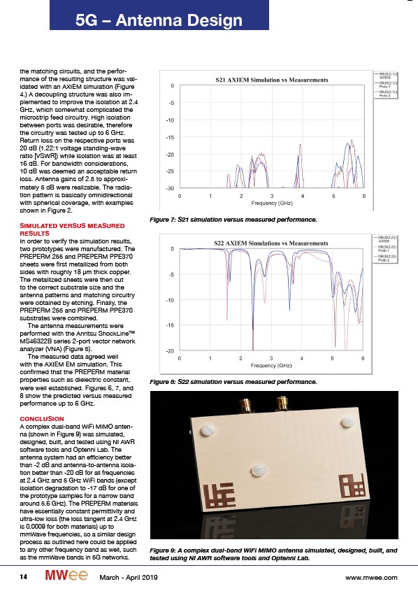
CONCLUSION
A complex dual-band WiFi MIMO antenna
(shown in Figure 9) was simulated,
designed, built, and tested using NI AWR
software tools and Optenni Lab. The
antenna system had an efficiency better
than -2 dB and antenna-to-antenna isolation
better than -20 dB for all frequencies
at 2.4 GHz and 5 GHz WiFi bands (except
isolation degradation to -17 dB for one of
the prototype samples for a narrow band
around 5.6 GHz). The PREPERM materials
have essentially constant permittivity and
ultra-low loss (the loss tangent at 2.4 GHz
is 0.0009 for both materials) up to
mmWave frequencies, so a similar design
process as outlined here could be applied
to any other frequency band as well, such
as the mmWave bands in 5G networks.
Figure 7: S21 simulation versus measured performance.
Figure 8: S22 simulation versus measured performance.
Figure 9: A complex dual-band WiFi MIMO antenna simulated, designed, built, and
tested using NI AWR software tools and Optenni Lab.
14 MW March - April 2019 www.mwee.com
/www.mwee.com