Low Power Wireless
Maximizing the Range of Low-Current Wireless
Designs
By Martin D. Stoehr, Manager, Strategic Applications, Maxim Integrated
The longest wireless communication
link ever created by humankind occurs
between the NASA/JPL Voyager 1 space
probe and the 70m Goldstone Deep
Space Network (DSN) radio antenna
located in southern California. Voyager 1
was launched in September 1977 and having
been on an extended scientific mission
for more than 41 years, it is currently
over 21.5 billion km (13.3 billion mi) from
Earth. Yet even with this vast distance
between the planetary probe’s powerful
transmitter and the sensitive Earth-bound
receiver, the radio link budget is not much
different from one used by a short-range
devices (SRD) system designer.
THE TRANSMITTER
The first step in estimating and optimizing
an SRD link budget starts with the
transmitter. A system designer needs to
know the effective power of the transmission
block, typically measured at a power
amplifier’s (PA) output using units of dBm
(power radio referenced to 1 milliWatt).
Next, any interconnect and filtering losses
should be subtracted from this power.
Then for the transmitter portion of the link
budget the antenna gain or loss must be
included; this gain is noted in units of dBi
(dB power ratio referenced to an ideal
isotropic antenna).
On Voyager 1, the transmitter output
is around 12.6 W or about +41 dBm. For
the probe, losses come from pointing
errors rather than the more common
interconnect losses experienced by Earth
bound designers, but the effect is the
same. In the case of Voyager, the pointing
loss is a diminutive 0.1 dB. For the antenna,
the space probe utilizes a huge,
directional dish with a 3.66m diameter,
pointed at our home planet, which provides
an astounding +48 dBi of gain. The
overall transmitter system power output
from the Voyager 1 probe is a remarkable
+89 dBm!
Compare Voyager 1 to a typical shortrange
system and you find that the typical
output power of an SRD transmitter PA is
a much more modest +10 dBm (0.01 W).
The interconnections and filtering
commonly required to meet regulatory
limitations such as occupied bandwidth
and spurious responses would typically
reduce the output power by about 2 dB.
The final stage in the SRD transmitter
suffers from a less than ideal implementation:
a small footprint, omnidirectional
antenna which will radiate at a loss of
about -10 dBi to -15 dBi, or worse. These
values place the total transmission power
of an SRD design at around -7 dBm.
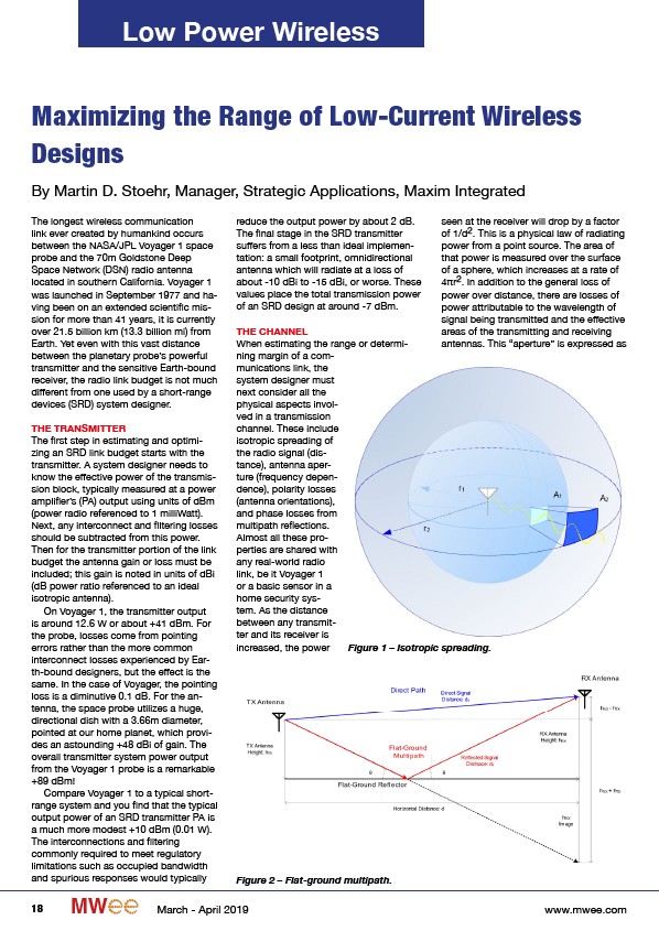
THE CHANNEL
When estimating the range or determining
margin of a communications
link, the
system designer must
next consider all the
physical aspects involved
in a transmission
channel. These include
isotropic spreading of
the radio signal (distance),
antenna aperture
(frequency dependence),
polarity losses
(antenna orientations),
and phase losses from
multipath reflections.
Almost all these properties
are shared with
any real-world radio
link, be it Voyager 1
or a basic sensor in a
home security system.
As the distance
between any transmitter
and its receiver is
increased, the power
seen at the receiver will drop by a factor
of 1/d2. This is a physical law of radiating
power from a point source. The area of
that power is measured over the surface
of a sphere, which increases at a rate of
4πr2. In addition to the general loss of
power over distance, there are losses of
power attributable to the wavelength of
signal being transmitted and the effective
areas of the transmitting and receiving
antennas. This “aperture” is expressed as
Figure 1 – Isotropic spreading.
Figure 2 – Flat-ground multipath.
18 MW March - April 2019 www.mwee.com
/www.mwee.com