Low Power Wireless
1 to DSS-14 link budget leaves us about
+19 dB of margin between the RSS and
the sensitivity of the receiver.
In our SRD system, the receiver
commonly has a less-than-ideal antenna,
with somewhere around -5 dBi for
a common omnidirectional ‘whip.’ After
including minor interconnect losses of
-1 dB, the RF engineer is finally able to
compute the power at the input to the
receiver’s LNA—in this example it sits at
-109 dBm. Most ISM receivers have sensitivities
in the -105 dBm to -115 dBm
range. By selecting a common ASK receiver
with a sensitivity of -110 dBm we
can now determine how much margin
the link budget predicts. In this case the
designer is left with only +1 dB of SNR—
the receive power is at the very edge of
being detectable!
HOW TO IMPROVE RANGE
How does the SRD designer get a little
more margin for the 100m range?
What should be apparent in the
walk-through of the signal chain is that
physics dominates the losses in the
communications channel and the system
designer has no control of the system
between the transmitter and the receiver.
Free-space path loss, flat-ground multipath,
obstructions, even weather and
moving objects (people, automobiles,
etc.) will have an impact on the channel,
leaving the system designer at the mercy
of the application’s environment. Since
the channel cannot be controlled, only
the transmitter and the receiver remain
as the system blocks where a wireless
designer can have influence.
To some extent, even aspects of
these radio blocks are out of the RF
engineer’s control. Items such as
maximum radiated power and spectral
purity (occupied bandwidth and spurious
signals/harmonics) are often limited
by regulatory bodies (FCC, ETSI, etc.).
Likewise, form and function are common
constraints imposed by the aesthetics
and physical placement of the applications’
radios. Giant antennas are fine
for space probes, but hanging off every
exterior window and door of a home
is not a favorable design feature for a
security system. So often, the first radio
hardware to suffer from these aesthetic
design constraints are the antennas.
Commonly, the next constraint placed
on the system designer is usually the
battery. Again, due to size limitations the
power supply design starts to impose
limitations on receiver sensitivity, but
more often, the transmitter power is
limited by battery life requirements.
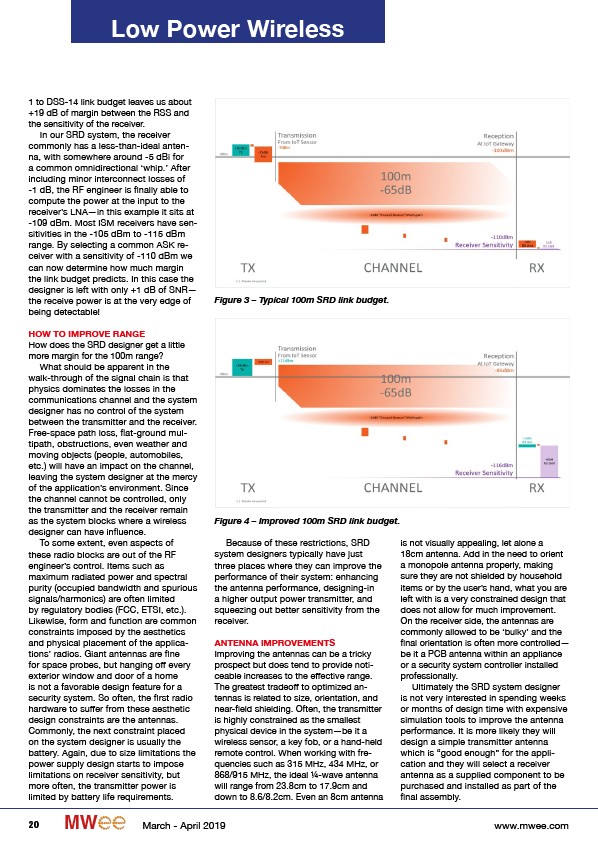
Figure 3 – Typical 100m SRD link budget.
Figure 4 – Improved 100m SRD link budget.
Because of these restrictions, SRD
system designers typically have just
three places where they can improve the
performance of their system: enhancing
the antenna performance, designing-in
a higher output power transmitter, and
squeezing out better sensitivity from the
receiver.
ANTENNA IMPROVEMENTS
Improving the antennas can be a tricky
prospect but does tend to provide noticeable
increases to the effective range.
The greatest tradeoff to optimized antennas
is related to size, orientation, and
near-field shielding. Often, the transmitter
is highly constrained as the smallest
physical device in the system—be it a
wireless sensor, a key fob, or a hand-held
remote control. When working with frequencies
such as 315 MHz, 434 MHz, or
868/915 MHz, the ideal ¼-wave antenna
will range from 23.8cm to 17.9cm and
down to 8.6/8.2cm. Even an 8cm antenna
is not visually appealing, let alone a
18cm antenna. Add in the need to orient
a monopole antenna properly, making
sure they are not shielded by household
items or by the user’s hand, what you are
left with is a very constrained design that
does not allow for much improvement.
On the receiver side, the antennas are
commonly allowed to be ‘bulky’ and the
final orientation is often more controlled—
be it a PCB antenna within an appliance
or a security system controller installed
professionally.
Ultimately the SRD system designer
is not very interested in spending weeks
or months of design time with expensive
simulation tools to improve the antenna
performance. It is more likely they will
design a simple transmitter antenna
which is “good enough” for the application
and they will select a receiver
antenna as a supplied component to be
purchased and installed as part of the
final assembly.
20 MW March - April 2019 www.mwee.com
/www.mwee.com